- +91 9041070535
- +91 9878647005
- info@mehtapowerelectrical.com


Transformers for Every Application
From compact distribution units to high-capacity power
transformers — engineered to ISI standards and built for India’s
toughest infrastructure projects.
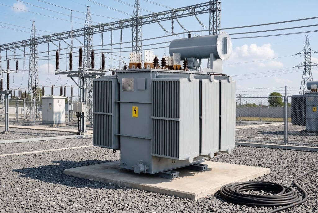
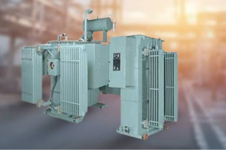
Oil Cooled Distribution Transformer
Oil Cooled Distribution Transformer (Distribution Transformer with Off Circuit Tap Changer)
RANGE : Upto 10 MVA in 11, 22, 33 & 66 KV Class.
Mehta Power Electrical covers a wide range of Oil Filled Distribution Transformers with Off Circuit Tap Changer (up to 5000 KVA in 11 KV & 33 KV Class) conforming to the international standards of quality and safety. These transformers are designed and developed using latest technologies and can be provided with a variety of terminations so as to suit the requirements for new installation or replacement.
Optimum efficiency is ensured by delicate proportioning of core and winding looses using CRGO M3 to M5 MOH Lamination, Electrolytic Grade 99.9% pure copper, with Transposition in L.V. coil for current sharing in parallel Conductors, Electric grade press paper, boards and mineral oil. Thus better regulation is achieved resulting in longer life. Careful designing also reduces noise level to the minimum.
| STANDARD SPECIFICATIONS | |
|---|---|
| Capacity | Up to 10 MVA |
| No. of Phases | 3 Phase |
| Frequency | 50 Hz. |
| Voltage Range | 11 KV / 22 KV / 33 KV / 66KV |
| Tapping | +5% to -5% Taps on H.T. Side in steps of 2.5% each. |
| Insulation | Class ‘A’ |
| Vector Group | Dyn 11 |
| Duty Cycle | Continuous |
| Winding | Copper Wound |
| Terminals | As per required |
| STANDARD FITTINGS | |
|---|---|
| Rating & Diagram plate | Earthing terminals |
| Lifting lugs | Thermometer pocket |
| Oil Conservator with drain plug | Air release hole with plug |
| Voltage Range | 11 KV / 22 KV / 33 KV / 66KV |
| Oil Level indicator | Explosion vent with diaphragm |
| Top-filter Valve | Inspection cover. |
| Silica gel breather | Drain –cum-bottom-filter valve |
| Cooling radiators | Uni / Bi- directional rollers |
| OPTIONAL FEATURES | |
|---|---|
| Buchholz relay with alarm and trip contact | Magnetic oil level gauge with alarm contact |
| Pressure Release Valve | Marshalling box to house O.T.I. and W.T.I |
| Cable Box on H.T. Side | Cable Box on L.T. Side. |
| Oil Temp. Indicator with alarm & trip contact | RTCC (Remote Tap Changer Control) Cubicle |
| Winding Temp. indicator with alarm & trip contact | Electronic Automatic Voltage Controller |
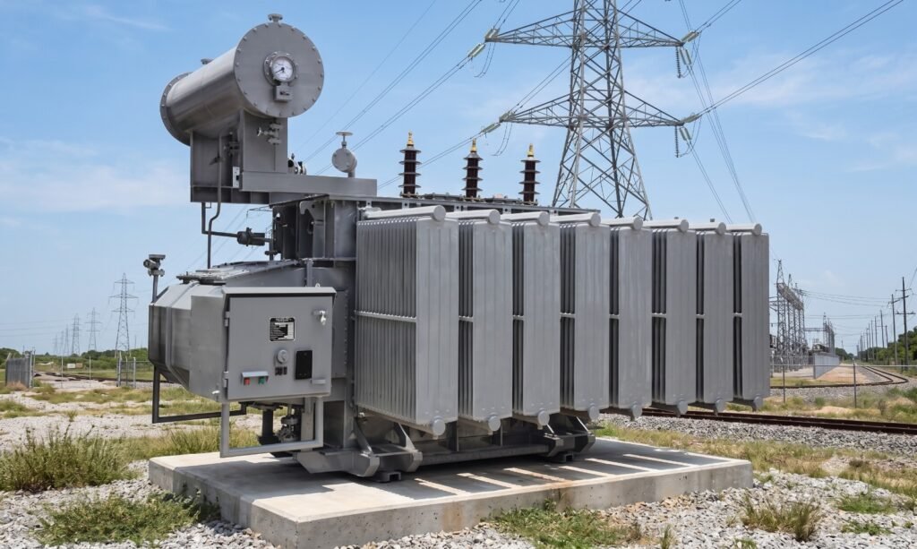
Oil Cooled Distribution Transformer with OLTC
Oil Cooled Distribution Transformer with OLTC(Distribution Transformer with On Load Tap Changer)
RANGE : Upto 10 MVA in 11, 22, 33 & 66 KV Class.
Mehta Power Electrical covers a wide range of Oil Filled Distribution Transformers with On Load Tap Changer (up to 10000 KVA in 11 KV & 33 KV Class) conforming to the international standards of quality and safety. These transformers are designed and developed using latest technologies and can be provided with a variety of terminations so as to suit the requirements for new installation or replacement.
Optimum efficiency is ensured by delicate proportioning of core and winding looses using CRGO M3 to M5 MOH Lamination, Electrolytic Grade 99.9% pure copper, with Transposition in L.V. coil for current sharing in parallel Conductors, Electric grade press paper, boards and mineral oil. Thus better regulation is achieved resulting in longer life. Careful designing also reduces noise level to the minimum.
| STANDARD SPECIFICATIONS | |
|---|---|
| Capacity | Up to 10 MVA |
| No. of Phases | 3 Phase |
| Frequency | 50 Hz. |
| Voltage Range | 11 KV / 22 KV / 33 KV / 66KV |
| Tapping | +5% to -5% Taps on H.T. Side in steps of 2.5% each. |
| Insulation | Class ‘A’ |
| Vector Group | Dyn 11 |
| Duty Cycle | Continuous |
| Winding | Copper Wound |
| Terminals | As per required |
| STANDARD FITTINGS | |
|---|---|
| Rating & Diagram plate | Earthing terminals |
| Lifting lugs | Thermometer pocket |
| Oil Conservator with drain plug | Air release hole with plug |
| Voltage Range | 11 KV / 22 KV / 33 KV / 66KV |
| Oil Level indicator | Explosion vent with diaphragm |
| Top-filter Valve | Inspection cover. |
| Silica gel breather | Drain –cum-bottom-filter valve |
| Cooling radiators | Uni / Bi- directional rollers |
| OPTIONAL FEATURES | |
|---|---|
| Buchholz relay with alarm and trip contact | Magnetic oil level gauge with alarm contact |
| Pressure Release Valve | Marshalling box to house O.T.I. and W.T.I |
| Cable Box on H.T. Side | Cable Box on L.T. Side. |
| Oil Temp. Indicator with alarm & trip contact | RTCC (Remote Tap Changer Control) Cubicle |
| Winding Temp. indicator with alarm & trip contact | Electronic Automatic Voltage Controller |
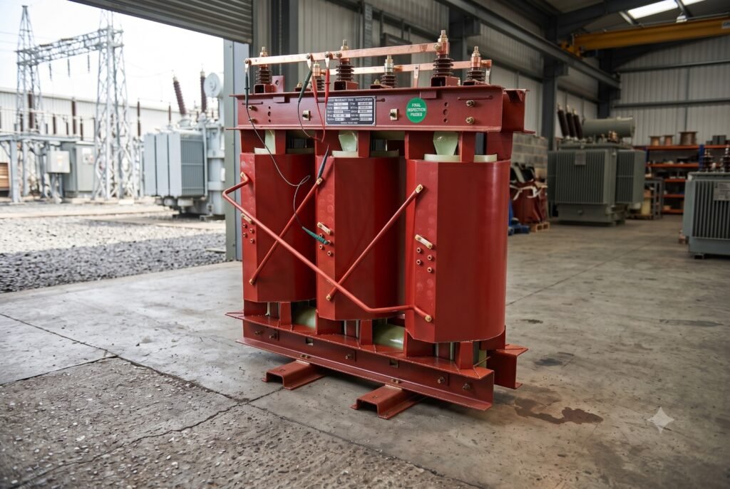
Cast Resin Transformers
Cast Resin Trasformers
RANGE: Ratings 25 KVA to 5,000 KVA. – upto 33 KV
In view of the requirement of Indian Industry, we have introduced Mehta Power Electrical Cast Resin (Dry Type) Transformers. This introduction supplements our existing product viz. Vacuum Resin Impregnated Dry Type Transformers. Dry Type Transformers of both the above varieties are in use.
The Company has Resin Impregnated Dry type Transformers up to 5 MVA, 11 KV Class.
In view of the requirement of Indian Industry, we have introduced Power Star Cast Resin (Dry Type) Transformers. This introduction will supplement our existing product viz. Vacuum Resin Impregnated Dry Type Transformers. Dry Type Transformers of both the above varieties are in use in the Indian Industry.
They manufacture Cast resin Power and Distribution Transformers, Converter Transformers, Transformers with On Load Tap Changers (OLTC), Motor – starting Transformers, Testing Transformers, etc. Their specialty is to make special transformers to meet customers’ requirements.
| Ratings | |
|---|---|
| Ratings 25 KVA to 5,000 KVA. - upto 33 KV H.V. Voltages : | |
| 3.3, 6.6, 11, 22, 33KV. Voltages lower than 3.3kv on request. | |
| L .V. VoltagesS | |
|---|---|
| 433 V and around. Voltages up to 11KV on request. | |
| Insulation Class | |
|---|---|
| F (90°C T`emp. Rise), Others on request. | |
| Applicable Standards | |
|---|---|
| IS1I171 / IEC 60726 | |
| Duty | |
|---|---|
| Distribution & Power Transformers. | |
| Rectifier/ Thyristor duty. | |
| Induction Furnace Duty. | |
| Lighting, Isolation. | |
| Generator Excitation. | |
| Advantage of Cast Resin Transformers | |
|---|---|
| No Fire Hazard. | |
| Near Load Center or even near to load. | |
| Low as transformer is near to load. Also cable drop is reduced. | |
| Negligible smoke generation. | |
| Suitable for indoor use as no fire risk. | |
| Can be fitted outdoor in IP 45 enclosure. | |
| Suitable for as low as -25° C ambient temperature. | |
Manufacturing Process
Manufacturing Process Core
Three limb core construction is used. Core sheets conforming to drawings are made from Cold Rolled Grain Oriented (CRGO) Silicon Steel sheets. Individual sheets come duly coated with inorganic insulation. Circular Core cross section is used which is obtained by assembling number of steps of different widths. Number of steps and step widths are optimized to gain maximum advantage. Mitred joints are used between the limb plates & yoke plates. Fibre -glass tape banding hold the core tight and reduce the noise level. Treatment given to the completed core, protects it from atmospheric corrosion.
Windings
Both the H.V. and L.V. windings are made from copper conductors. Round wire, rectangular strip or foil is used depending on current to be carried. Layer type or cross over type winding is used depending on current / voltage to be handled. Windings are cast under vacuum.
On the H.V. side, inserts are provided to receive tap changing links. Inter connections between H.V. phases are obtained by links made out of copper tubes with their ends formed into lugs. These links are insulated by means of heat shrinkable tubes.
Protection
Protection against Overload/high winding temperature can be provided by Thermistors. ALARM and TRIP are provided, when required, by means of Thermistor or RTD sensors can be provided with 2 set points.
Automatic Servo Voltage Stabilizer (LT AVR)
THE CONSTRUCTION PROCESS
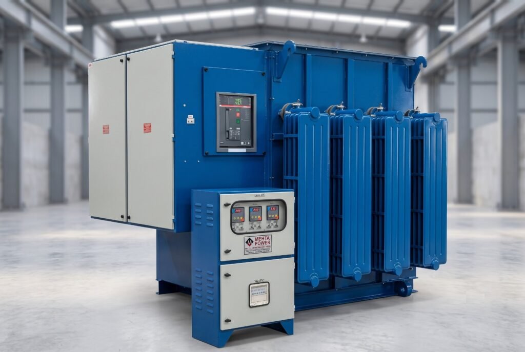
At the heart of the Voltage Stabilizer are the regulator coils. While some small capacity regulator coils are uncompensated, all larger capacity voltage stabilizer regulator are fully compensated.
Compensation is a method where by the naturally high reactance of long thin coils, used in the construction of the ‘Reliable’ Regulator coil is limited to a low value across the range of variation.
Limiting the reactance tends to produce a linear variation in the output voltage of the regulator, across the range of operation. Contact pick up tracks are machined onto the faces of the coils. Depending on the required output arrangement there may be tracks on both sides of the coil, or only on one side.
The coils are then mounted on a core of grain oriented silicon steel laminations.
The core and coils are mounted in a steel framework that allows roller contacts to be presented to the coil faces at a constant pressure across the range of operation.
To achieve variation in the output voltage the roller contacts are moved along the coil face. Roller contacts are housed within retaining assemblies that are in turn fixed to a carrier board. The carrier board’s position is maintained by a chain drive system that is in turn attached to the drive mechanism, either hand- or motor-driven.
COOLING
The construction of the ‘Reliable’ Regulator assembly allows the same basic unit, with only minor changes, to be used either immersed in cooling fluid, or directly air-cooled.
For the larger power ratings of regulator, fluid immersion is used exclusively.
Linear Rolling Contact Type Regulator
Step Down & Buck/Boost Transformer Assembly
Carbon Roller Assembly
| TECHNICAL SPECIFICATION |
||||
|---|---|---|---|---|
| Capacity | 30 kVA to 5000 kVA | |||
| Technology | Linear Type On-Load Voltage Regulators with stepless Regulation (also referred as Vertical Rolling Contact or Columnar Design) | |||
| Control Module Microprocessor based No. of Phases |
Three-Phase | |||
| Frequency | 50 / 60 Hz ± 5% | |||
| Type | Balanced (Common Control for all three phases. Suited for Balanced input supply & up to 40% Unbalanced load) Unbalanced (Individual Phase Control. Suited for unbalanced input supply & unbalanced load) | |||
| Load Variation | Admitted from 0 to 100% | |||
| Installation | INDOOR/OUTDOOR as per site requirement | |||
| Cooling | Natural Oil-Cooled, ONAN (available in all models) Air-Cooled, Natural / Forced (available in select models) | |||
| Output Voltage | 400V±1% (Ph-Ph) / 230V±1% (Ph-N) | |||
| Input Voltage | 350-450V | 340-460V | 330-470V | 320-480V |
| 300-500V | ||||
| Efficiency | ~99.5% | ~99% | ~99% | ~98.5% |
| Duty Cycle / Life | Designed for 100% Continuous Duty Cycle & for a life of 25-30 years at extreme conditions. | |||
| Response Time Less than 2 - 3 milliseconds. Correction Rate |
8-15 Volts/second (upto 500kVA) and 8-12 Volts / second (above 500kVA) | |||
| Waveform Distortion Virtually Nil Ambient Temperature |
-10 to 45°C | |||
| Temperature Rise | Designed for 30°C rise above ambient at full load (against IEC std. of 45°C) | |||
| Mounting | On Unidirectional Wheels |
OUTPUT
Due to the flexibility of the design several arrangements can be provided. These range through single phase or three phase to double output for buck boost arrangements where the output of the regulator starts at a maximum voltage, decreases to zero, and then again increases in voltage but with the polarity reversed.
Buck boost connection is used where the minimum output voltage is above zero volts. Basically the connection comprises of two fixed ratio transformers and a double output voltage regulator.
One fixed ratio transformer (commonly referred to as the Main Transformer) has an output voltage approximating to the mid-point of the range required. The second fixed ratio transformer (commonly referred to as the Buck Boost Transformer) has an output voltage approximating to the difference between mid-point, and minimum / maximum required voltage, and there output windings are connected in series. The input winding of the buck boost transformer is connected across the two outputs of the regulator.
With the roller contacts located at one end of the regulator a maximum voltage at a specific phase relationship to that of the fixed ratio transformers is produced.
The transformers are arranged so that in this condition the output voltage of the buck boost transformer is subtracted from the output voltage of the main transformer.
This provides the minimum output voltage of the arrangement.
As the roller contacts are moved to the centre of the regulator the output voltage of the regulator, and hence the buck boost transformer approximates to zero. The combined output of the arrangement is therefore the output voltage of the main transformer.
Continuing to move the roller contact in the same direction will increase the regulator output voltage. In addition the polarity of the voltage will have reversed so that the output voltage of the buck boost transformer is now added to that of the main transformer. By this means the maximum output voltage of the combination is achieved.
DUTY
The Mehta Power Electrical Regulator has good short term overload capacities. The equipments are designed for 100%duty cycle.
Almost any duty can be catered for. If you have specific requirements that you wish to discuss please contact our sales force.
| CONTROL | ||||||||
|---|---|---|---|---|---|---|---|---|
| Input Voltage | 360-450V | 350-460V | 340-460V | 320-460V | 300-460V | 280-460V | 260-460V | 240-460V |
| Efficiency (as calculated with tolerance) |
99.60% | 99.50% | 99.35% | 99.00% | 98.70% | 98.20% | 97.60% | 97.20% |
Technical Advantages
- Low Replacement Cost.
- Undistorted output characteristics ie. no wave from distortion.
- Moving parts on L.T. side and it’s mass is extremely low, only few Ib-inch torque.
- Energy Saving from 5-10% depending upon the voltage variation and number of working hours.
- High efficiency (about 99%) and minimum no-load losses ± Simplicity and Flexibility of design.
- On Load Step less Voltage Variation with AUTO/SEMI/MANUAL Mode facility.
- Long Service Life of 30 – 35 Years.
- Regulating coils are wound with rectangular conductors on their edge, thus giving high mechanical strength compared to other designs.
APPLICATIONS OF VOLTAGE REGULATORS
Pharmaceutical Units, Cold Storages, Rolling Mills, Textile Mills, Paper Mills, Tube Mills, Rice Shellers, Rubber Industries, Food Processing Units, Oil & Vanaspati Plants, Footwear & Leather Units, Tea Gardens, Distilleries & Beverages, Hospitals & Nursing Home, Clubs, Hotels, High Rise Buildings, Furnace Transformers, Test Rooms, Glass Industries, Research Stations, Chemical Industries
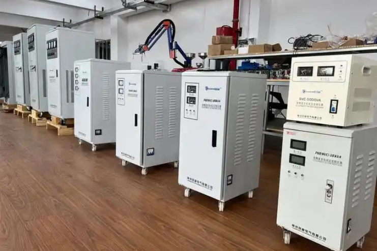
Electro Plating Rectifier Oil Cooled
RECTIFIER (D.C. POWER SUPPLIES) - ROLLING CONTACT TECHNOLOGY
With Its easy convertibility from one voltage to another A.C. (Alternating Current) reigns supreme in the generation transmission and distribution Systems. Yet DC (Direct Current)/ DC power supplies for Electroplating Plants, Electro chemical plants, Copper, Aluminium & Zinc Refining all requires modest Voltage and high DC current. DC power is also required in other Industrial processes like Hydrogenation & Electrolysis. Such continuous Power Industries look for a ‘Mehta Power Electrical’ economical and trouble free form of DC Power supply Systems. ‘Mehta Power Electrical’ offers a complete range of Rectifier Equipments for all such application and provides Engineering, Design and Technical support in choosing the right solution / Equipment.
APPLICATIONS
- Electroplating (Chrome Plating, Hard Chrome Plating, Zinc Plating, Nickel Plating, Copper Plating, Gold Plating, Silver Plating etc.)
- Cathode Electro Deposition (C.E.D. Coating)
- Anodizing Anodized Electro Coloring, Hard Anodizing.
- Heating Furnace, Magnetization, Ionization.
- Electroforming
- Hydrogenation, Electrolysis
- Copper, Aluminium & Zinc Refining
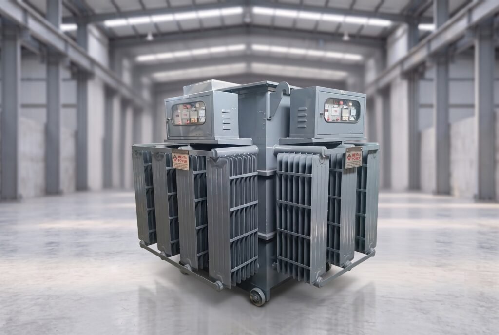
| GENERAL SPECIFICATIONS | ||
|---|---|---|
| AC Input | Voltage | 380/440 volts |
| Phase | 3 | |
| Frequency | 50 Hz | |
| Customization | High Voltage Input up to 11 KV | |
| DC Output | Voltage | 8, 12, 16, 24 volts, 50 volts, 100 volts, 150 Volts, 200 Volts & 500 Volts |
| Current | 0-30000 Amps | |
| Customization | Power Systems up to 30000 Amps and voltages up to 500 V DC are available. |
Efficiency: Mehta Power Electrical Supplies are highly efficient with typically efficiency between 95-98% depending upon the DC voltage of the Unit.
Power Factor: 90% Rated output.
Rating: All components are rated as a standard for 100% continuous full load service in an ambient Temperature of 50°C.
Temperature: ‘Mehta Power Electrical’ design its systems for a maximum rise of temperature of 35°C at the top of the oil with an ambient temperature of 50°C.
Ripple Factor: As we use Double Star Hexa Phase Circuit with Interphase Transformer. So the ripple content is always Less than 4.5%.
TRANSFORMER
Winding Material :– Splice free, electrolytically pure copper 99.9%
Core Material: – Low Loss, High quality, Grain Oriented Silicon Steel provides good flux and low eddy current losses
Insulation Material : – ‘A’ Class Insulation is used for ONAN systems.
Process :- The coils are vacuum impregnated by Varnish and then baked to cure. Varnishing provides additional electromechanical Strength. All coils are wound for stress distribution under fault conditions to provide superior mechanical strength.
Cooling: – ‘Mehta Power Electrical’ supplies are designed for optimum low loss/efficient operation and employ specially designed natural oil cooling to remove the heat generated during operation.
Controls: – The following are examples of typically required Control configurations. ‘Mehta Power Electrical’ is committed to working with each Customer on an individual basis to ensure your Control requirements are satisfied.
- Standard Control (D. C. Metering, Push Buttons and Indicator lights in a panel on the machine)
- Manual – Remote
- Centralized control Panel for Number of Systems
- Constant Voltage Controller /constant current controller
- Zero Run Down System
- Ampere Hour Meter/Ampere Minute Meter
Semiconductors: ‘Mehta Power Electrical’ selects its semiconductors with an appropriate 200% safety factor to provide the ultimate in reliability. This design criterion limits the junction temperature of semiconductor to typically less than 80 °C , thus enhancing the life of the equipment.
MS Shell : The enclosure i.e. mild steel steels are fabricated with 8/10/12 SWG HR sheets. The requisite supports along with seam welded cooling fins are provided to dissipate the heat produced. The housing is checked for leakage with pressure testing. The job is then paint finished inside and outside by degreasing and acid resistant Epoxy Paint. Standard Paint will be BS Grey. Change of shade on request.
Ripple: Standard 6 pulse DC Rectifier will contain less than 5% RMS AC Ripple when operated at Rated Voltage and Current.
Training: Mehta Power Electrical’s service Engineer may instruct our customer’s operator and Maintenance personnel during the commissioning /start of the unit or during final test at our works. This can be operational training and / or full Maintenance repair training.
Spare Parts: ‘Mehta Power Electrical’ maintains a considerable spare parts inventory and has the appropriate factory approved spare parts on hand and ready for your use to assure maximum uptime of your process. Mehta’s power supplies are designed for decades of trouble free performance when the installation and maintenance guidelines contained in the service manual are followed.
D.C. BUS BAR: ‘Mehta Power Electrical’ uses Electrolytically pure Copper/ Aluminium bus bar exclusively in our rectifier systems. Bus Block with bolted joints and flexible connections are designed to minimize bus losses and to match the client’s application requirement. The laminated bus structure designed maintain a low bus impedance and low voltage over shoot.
QUALITY CONTROL
Each piece of equipment we build is rigorously tested and put through a systematic quality control examination prior to dispatch. Our test facility utilize state of art equipment to verify that the Power Supply you receive is exactly what you ordered. Our staff of highly competent test technicians performs a full range of operational and functional testing and maintains complete documentation of all test procedures and results. Prior to dispatch/ shipment a final quality control inspection is performed.
RECTIFIERS (IGBT BASED)
RECTIFIER (D.C. POWER SUPPLIES) - IGBT BASED RECTIFIERS
Mehta Power Electrical make IGBT Rectifiers are designed to meet industrial application requirements. An insulated –Gate Bipolar Transistor (IGBT) uses relatively high frequency switching and pulse width modulation (PWM) technology for voltage and current regulation whilst a silicon controlled rectifier (SCR) uses relatively low frequency switching and phase shift technology.
Mehta Power Electrical make IGBT based Rectifiers are smaller in size and lighter in weight, more energy efficient and more cost effective compared to SCR & Rolling contact type Technology”
APPLICATION FIELD
The IGBT Rectifier is used for Plating, Anodizing, Electro polishing, Electrolysis, Electro winning, Electro Refining, Cathode Electro Deposition (C.E.D. Coating), Tinning, Electronic Cleaning, Pickling, Surface Coloring, Cathode Protection.
HEATING
- Inductive Heating
- D.C. Heating
- Single Phase AC Heating
WATER TREATMENT
- Waste Water Treatment
- Sea Water Treatment
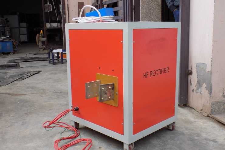
| TECHNICAL SPECIFICATION | |
|---|---|
| Input Voltage | 3 Phase, AC 380V, 480V, 415V, 220V ±10%, 50 -60Hz. |
| Output DC Voltage | Up to 400V |
| Output DC Current | Up to 20000Amps. |
| Protection Class | IP31, on request up to IP44 |
| Efficiency | ≥90% @ rated output |
| Power Factor | ≥0.93 @ rated output |
| Ambient Temp. | Max. 50°C (Water Cooling), Max. 40°C (Forced Air Cooling) |
| Cooling | Water or forced Air Cooling |
| Regulation Range | Stepless at constant voltage or current 0-100% |
| Control Precision | Voltage / current less than 0.5% |
| Duty Ratio | Continuous operation at rated loads up to 2000m altitude |
| Control Mode | Constant Current / Voltage /Power(AHM) |
| Operation Mode | Local/ remote |
| Relative Humidity | 15% -85% RH |
| Interface | RS485, RS232, MODBUS TPC, Profibus –DP, Profinet, Analogue 0-10V, Analogue 4 -20mA |
| Parallel Connection | No Limit |
| HMI | Touch Panel or Digital Meters /buttons |
PROTECTION FEATURES
- Overheat
- Output over voltage / under voltage
- Output over current
- Output short circuit
- Cooling water pressure (Single Phase Protection)
TRANSFORMER WITH BUILT IN HT AVR
HT TRANSFORMERS WITH BUILT IN AUTOMATIC VOLTAGE STABILIZER
It is a very altogether different product basically a combination of Standard Distribution Transformer and HT Automatic Voltage Regulator. The Standard Transformer with OLTC can correct limited voltage variation in certain steps where as Built-in operates steplessly monitoring the output voltage continuously.
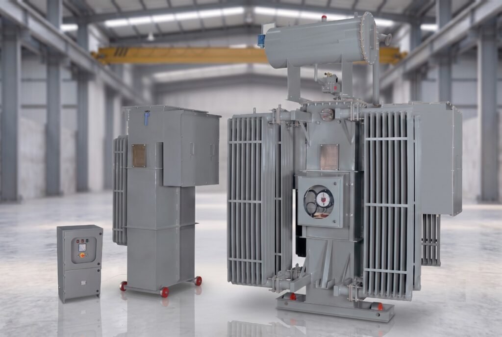
The incoming fluctuating H.T. supply is initially stabilized and then fed to the step down transformer and thereby the L.T. Output is maintained within ±1% accuracy. Built – in has the following advantages:
- Space saving
- Reduced Installation cost
- More efficiency
- Reduction in Electricity Bill
| STANDARD SPECIFICATION |
|---|
| Capacity : Up to 15000 KVA |
| No. of Phases : 3 Phase |
| Frequency: 50 Hz. |
| Voltage Class :11,22,33 KV |
| Voltage Range : + 20% to - 30% (or any voltage range as per site client requirements) |
| Technology: Stepless linear regulator type (Vertical rolling contact type) |
| Insulation :Class ‘A’ |
| Vector Group :Dyn 11 |
| Duty Cycle :Continuous |
| Winding :Copper Wound |
| Terminals :As per required |
Linear Rolling Contact Type Regulator
Step Down & Buck/Boost Transformer Assembly
Carbon Roller Assembly
| STANDARD FITTINGS |
|---|
| Rating & Diagram plate : Earthing terminals |
| Lifting lugs : Thermometer pocket |
| Oil Conservator with drain plug : Air release hole with plug |
| Oil Level indicator : Explosion vent with diaphragm |
| Top-filter Valve: Inspection cover. |
| Silica gel breather : Drain –cum-bottom-filter valve |
| Cooling radiators : Uni / Bi- directional rollers |
| OPTIONAL FEATURES | |
|---|---|
| Buchholz relay with alarm and trip contact | Magnetic oil level gauge with alarm contact |
| Pressure Release Valve | Marshalling box to house O.T.I. and W.T.I |
| Cable Box on H.T. Side | Cable Box on L.T. Side. |
| Oil Temp. Indicator with alarm & trip contact | |
| Winding Temp. Indicator with alarm & trip contact | Electronic Automatic Voltage Controller |
| ADVANTAGES |
|---|
| More efficient |
| Non toxic |
| Highly safe |
| Non flammable |
| Space saving by placing near the load end |
| Low Noise |
| Low Maintenance |
| Can be supplied with off circuit links |
| TECHNICAL ADVANTAGES |
|---|
| Very Easy to maintain – No Specialize Manpower is required. |
| Undistorted output characteristics ie. No wave from distortion. |
| Moving parts on L.T. side and its mass is extremely low, only few lb-inch torque. |
| Energy savings. |
| High efficiency (about 99%) and minimum no load losses. |
| Simplicity and flexibility of design |
| On load stepless voltage variation |
| Long service life |
| Impulse tested |
| Regulating coils are wound with rectangular conductors on their edge, thus giving high mechanical strength compared to other designs. |
| Low replacement cost. |
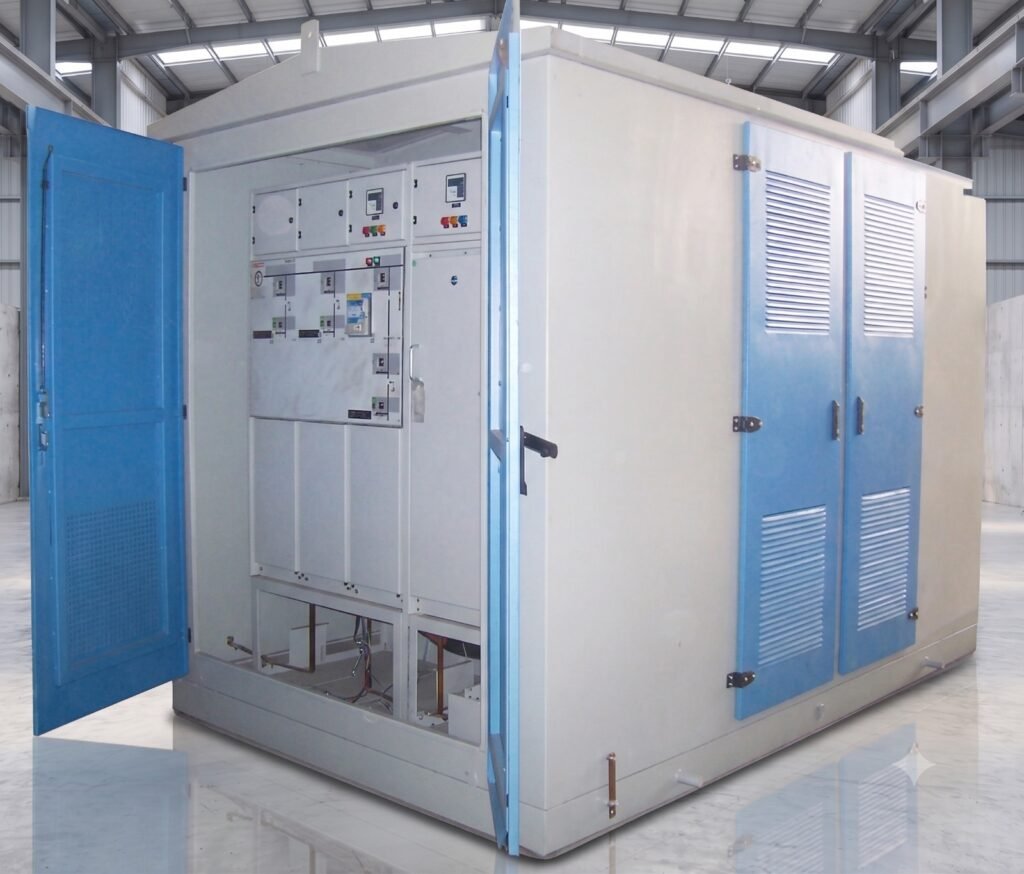
Package Subtation (Unitized Compact Substation)
Package Substation (Unitized Substation Transformer)
RANGE : Upto 5000 KVA in 11,22,33 KV Class.
Mehta Power Electrical offers qualitative range of PSS (Package Substation) or USS (Unitized Substation) Transformer from 100 KVA to 5000 KVA in 11,22,33 KV Class. These Package Substations are largely required for fire hazardous and compact places. A unitized substation is a compact arrangement, which simplifies conventional substation design. Substation housing is divided into three compartments i.e. the HV Compartment, the Transformer Compartment and the LV Compartment.
| Advantages |
|---|
| Reduced electrical losses as USS can be installed near load centres. |
| Total economy in cost. |
| Higher degree of safety and operational reliability is achieved by HT and LT switchgears and protective relays to avoid overloading. |
| Reduction in logistic cost as USS is delivered as a single unit. |
| Low civil / foundation cost. |
| UNITIZED SUB STATION CONFIGURATION COMPONENTS |
||
|---|---|---|
| HV Compartment | Transformer Compartment | LV Compartment |
| Extendible & Non Extendible MV Switchgear – Ring Main Unit (RMU) | Oil Immersed Transformer / Dry Type Transformer (VPI) | LV Distribution Board |
| Vacuum / SF6 Circuit Breaker, RMU & HV Fuse. | LT Control Panel with Incomer ACB & Outgoing MCCB | |
| RMU & Load Break Switch. | APFC Panel | |
| Protection & Metering Devices. | LV Switch fuse unit | |
| Current & Potential Transformer for Metering / Protection. | Instrumentation and Metering | |
| Illumination | ||
| Internal Lightning & Door Limit Switches, Tailor made enclosures mounted on the transformer under base to provide single lift complete installation with theft proof design. |
Applications
USS (Unitized Sub Stations) / Package Sub Station are ideally suited for new residential and commercial complexes as it can be placed on Ground, partially or totally below / above ground level. Mainly used by Power Utilities, Multiplexes, Hotels, Hospitals, Shopping Malls, Software Parks, Residential Complex, Airport etc.
Compact Substation
Skid Base Substation
Skid Mounted Substation
Containrized Mobile Substation
AC variable Supply/Testing Regulating Transformer
Testing Regulating Transformers / A.C. Variable Supply
With vast experience in design, skilled workforce and most modern infrastructure, we manufacture Testing Regulating Transformers / A.C. Variable supply Equipment which is used to vary the 11kV/22kV/33kV to 400/440V (Variable) with capacity up to 5000 KVA.
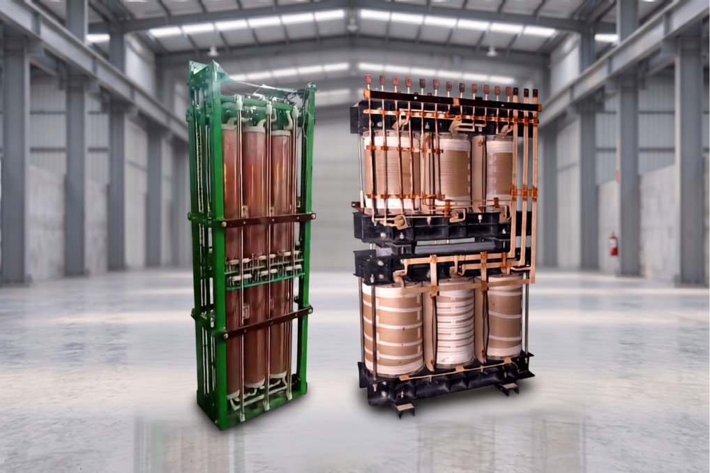
These Testing Regulating Transformers are generally used for testing of Motors, Generators, and other special purpose testing.
Linear Rolling Contact Type Regulator
Step Down & Buck/Boost Transformer Assembly
Carbon Roller Assembly
Electrical Panels
Electrical Panels
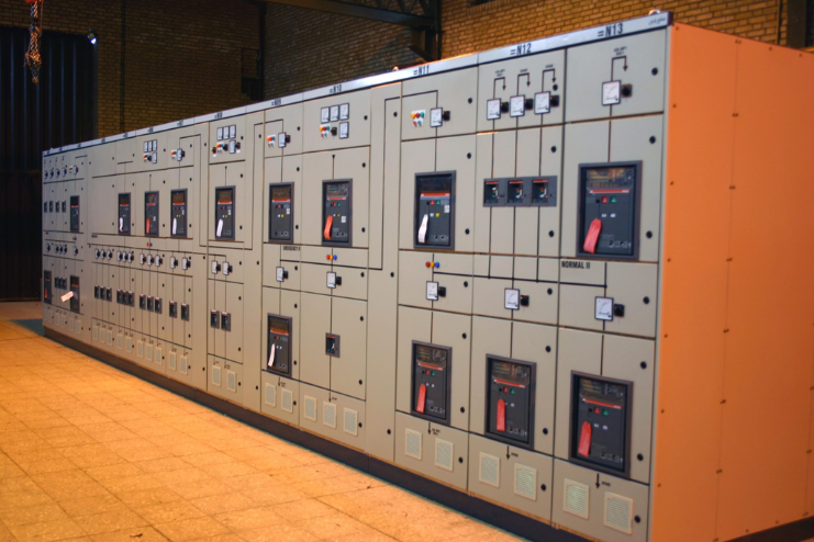
Mehta Power Electrical manufacture a wide range of LT Panels as per Indian Standards. We offer Panels with diverse specification options for a highly customzed panels upto 6300 amps having fixed and draw out types, including single/double front type. The LT Panels conform to IS 8623-part 1:1993 & IEC 439-1:1985.
Our panels are designed to withstand high humidity, temperature, ambient service conditions and short circuits levels & these make our panels an ideal choice.
Our panels provides superior control & protection of low voltage power equipment & circuits in utility, industrial, commercial installations involving generators, motors, feeder circuits and distribution.
LT Panels
An electrical distribution board that receives power from generator or transformer and distributes the same to various electronic devices and distribution boards. Such panels are used in industries both for internal and external use and therewfore are quite rugged to withsatnd different climatic conditions. Our LT Panels are designed to work with low electricity consumption that makes them cost effective.
Sychronizing Panels
These panels work between two or more different power sources like DG sets to manage power supply. Synchronization helps in making different DG sets behave as a virtual single unit and eliminates sub-division of total load. It helps in transferring loas from one unit to another as during service period, so that the unit requiring service can be easily shut off. In this way the critical load need not be interrupted and there is no production loss. During low load we can run any single unit and synchronize more units as the load increases automatically.
Salient Features
- Fully compartmentalized design
- Easy to install, operate & require very less maintenance
- Cost Effective & Space Saving
- A high degree of Safety & operational reliability is achieved
- Tailored Configuration to meet client’s requirements
- Aesthetically enhanced look & designed to suit client’s requirement
- Designed to meet temperature rise limits
Safety
- Completely enclosed bus bar chambers
- Shrouded links in feeder compartments
- Dust & vermin proof construction
- Bus bar constructions to withstand high fault levels upto 70 KA
| Technical SPECIFICATION | |
|---|---|
| Application | Power Distribution |
| Construction | Moduler & Fixed Type |
| Type | Drawout Type / Fixed Type |
| Max. Rated Current | Up to 6300 Amp., 70 KA |
| Rated Voltage | 415/440 Volt |
| System Voltage | 690 Volt |
| Ambient Temperature | 50 °C |
| Degree Of Protection | Up to IP-65 or as per requirement |
| Busbar | Aluminium or Copper |
| Interleaved Design | For 4000Amp. & above |
| Our PCC Panels are functionally colour coded for easy identification of feeder |
a. Transformer I/C Feeder – Blue b. Diesel Generator Incomer Feeder – Orange c. Bus coupler Feeder – Off whited d. O/G Feeder – Siemens Gray or as per customer’s specifications |
Custom Orders Welcome
Need a Custom Specification?
We manufacture transformers to your exact requirements. Share your project details and our engineering team will get back to you within 24 hours.